Dan Perry - 4" Extended Street

DanPerryy

Well-Known Member
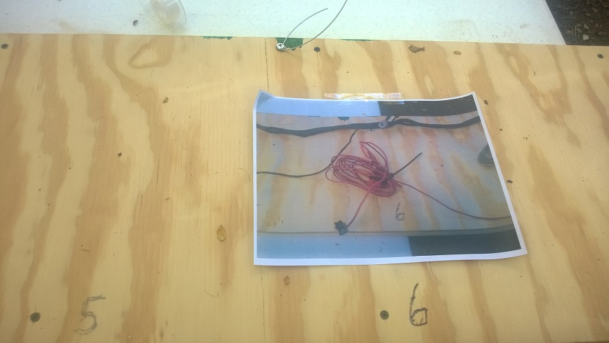
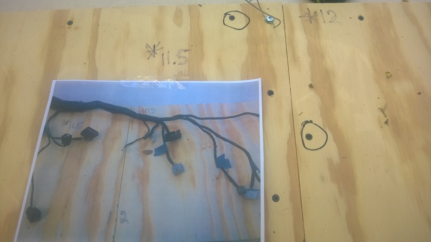
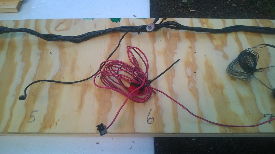
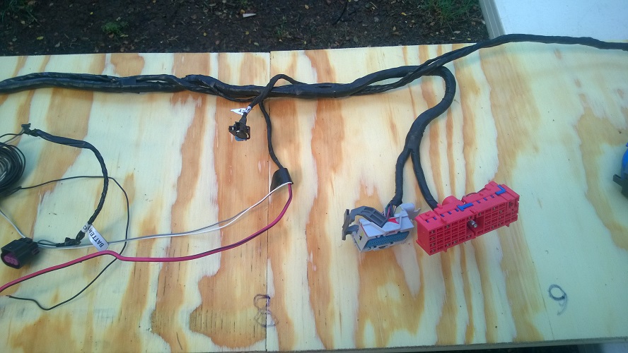
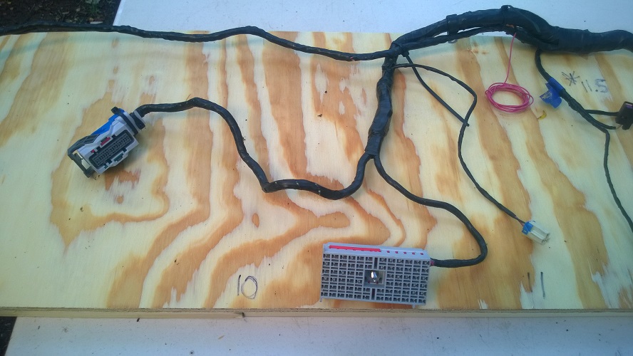
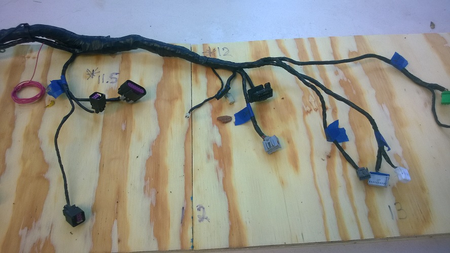
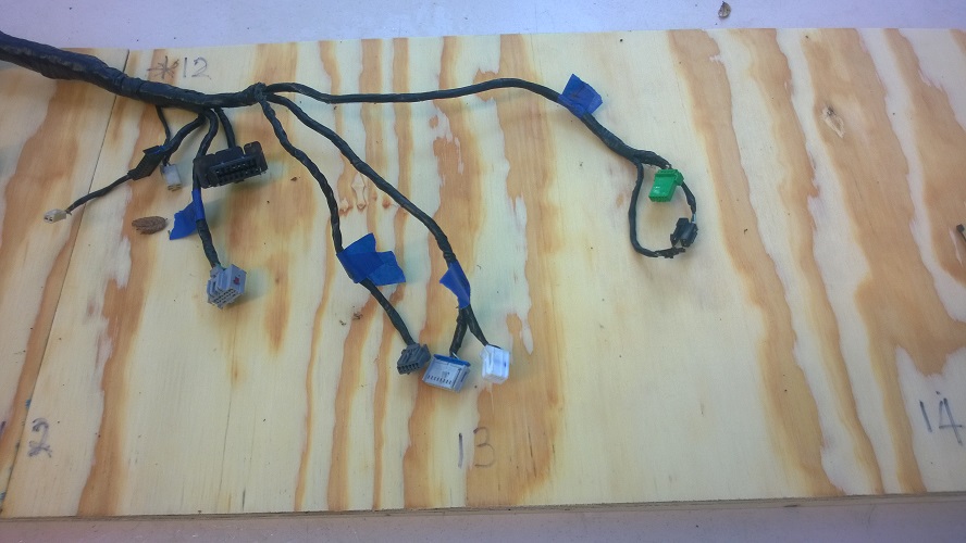
This afternoon - started on the main harness. I built a long table - 16' and marked it each foot. I then laid Lonny's and Adam's lender main harness on the table and took pictures of the finished main harness (see attached). I printed the pictures and taped them to the table at their proper position.

WP_20160803_015.jpg
WP_20160803_016.jpg
WP_20160803_017.jpg
WP_20160803_008.jpg
WP_20160803_009.jpg
WP_20160803_010.jpg
WP_20160803_011.jpg
WP_20160803_012.jpg
WP_20160803_013.jpg
WP_20160803_014.jpg
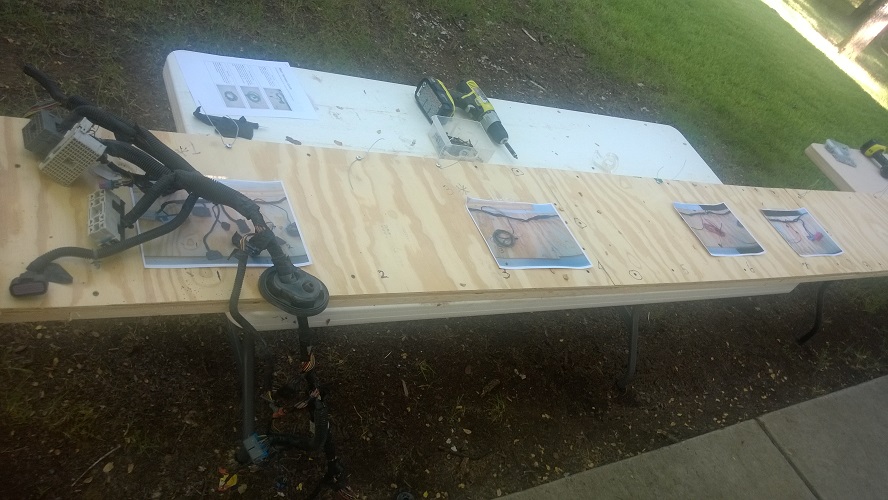
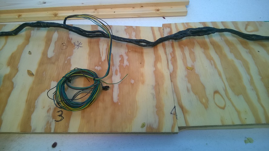
I attached some holding ties (a piece of bailing wire screwed down to the table) at positions along the completed harness.

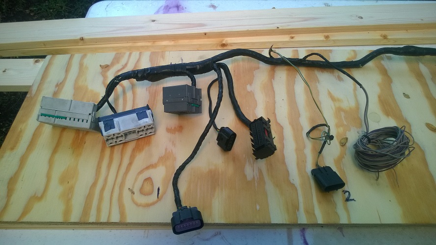
I printed out the thinning guide for the main harness. I then took the lender harness off the table and put my harness on the table tying it loosely starting from the engine end with the initial 8' of the table having connectors in about the proper final position. Then I started thinning. Some of the connectors (and cable that nned to be removed are a bit hard to identify from the pictures in the assembly guide. I will get closeup pictures of each removed connector for Adam to put in the guide.

This evening - in about 4.5 hours I screwed the table together, attached the ties and the pictures and nearly finished the thinning process. I just need to get the tail end wires removed (tail lights, trunk light, rear window defroster). I was surprised how quickly it went. I left about 4" on a saved connector when I cut a removal wired. I will go back and trim them or remove them from the connector. I could not get a final picture tonight as it got dark.
 

DanPerryy

Well-Known Member
I was an ET in the Navy, got a degree in EE after leaving the Navy. Being an electrical engineer does not make it any easier for me than anyone else. After all all we are doing is just disconnecting a bunch of hoses that happen to carry electrons.

I finished thinning the main harness, 2 more hours. It is really not that difficult. The only problem I had was I cut one wire that I should have left. It was a wire evidently for the license plate that was in a harness with the trunk release. I did take pictures or all the removed connectors.
Here id mu thinned harness still on the board
WP_20160804_023.jpg
WP_20160804_024.jpg
WP_20160804_025.jpg
WP_20160804_026.jpg
 
Last edited:

DanPerryy

Well-Known Member
This is the little connector in the trunk wire bundle that I remove accidentally - I think LP light
WP_20160804_021.jpg
 

DanPerryy

Well-Known Member
Another 4 hours on the harness. 2 hours was spent tracing our why one wire on my ECM connector was cut that was not cut on Lonny's. The rest of the time was spent cleaning up and further documenting the main harness. I am referencing back the pages of the service manual.
I will post the pictures I am using to build my harness. I have completed the rearend of the main harness now, Now starting on the front end of the main harness (cleanup and orientation of dash harness - already thinned - and then joining of the two harnesses.
 

DanPerryy

Well-Known Member
My wiring harness pictures. The page references are the service manual pages for a 2010 Cobalt. I will attach copies of each of the pages from the manual
1.jpg
2.jpg
3.jpg
4.jpg
5.jpg
6.jpg
7.jpg
 

DanPerryy

Well-Known Member
4 more hours, not yet connected the two harnesses. I had failed to remove the trunk lit release wires in the thinning process and had to trace out that circuit to find out what the connector was. Then the brake fluid wire, I did not realize that it came from the main harness - I was trying to find it in the dash harness. Then I added the power for the heater/blower motor in my car.
 

DanPerryy

Well-Known Member
4 more hours, the main and IP (dash harness) are now combined. Working on getting the front lights, horn integrated into the harness. Also parts of the HVAC harness, and heated seat circuit. I have some cleanup to do of the harness and I will post pictures when that is done.
 

DanPerryy

Well-Known Member
HVAC design - I'm making up a schematic but briefly - The HVAC blower (fan) I use from the Cobalt along with fan speed switch (stripped out of the dash HVAC board / panel). The blower uses the resistor assembly in the blower itself in conjunction with the switch to make the blower have 3-4 speeds. The heat and AC are just ON/OFF switches - full blast or nothing. Those switches will just open the heater valve or enable the actuation of the AC compressor (clutch). Im interlocking the switches so they don't work unless the blower is on (any speed).
 

DanPerryy

Well-Known Member
he engine radiator fan wires are in the engine harness, the wire needs to go to the front of the car. There is a body/engine harness connector set to connect the two harnesses. I pulled back my radiator fan wire in the engine harness and cut it to match the length of the wires in the body/engine connector. Then I stripped the connector for the HVAC power from the dash harness and used it for the radiator fan wire (this is a 30 amp connector). I then used the other end of the HVAC connector to run to the front of the car from my radiator. The result is two connectors next to each other to connect the engine harness to the body harness.
Adding horn relay activation wire to may body harness (this is not the wire to the horn from the horn releay) but the wire from the horn button (I'm putting a horn button the dashboard) to activate the horn relay.
I also added a cable from the front of the car to the back for towing lights. We have a small motorhome and I plan to flat tow the car. The cable will end at the rear in a connector next to a connector I put on the tail light circuit from the Goblin. The tail lights themselves will then plug into either of the connectors, one for driving the Goblin and one for towing the Goblin. The wiring still remains fun, I'm trying to make a real clean body harness. Nearly all wires accounted for now!!! 3 more hours - but I kind of step back an admire my work so I'm a bit slower.
This is the heater blower harness with the connector stripped (the connector plugs into the blower itself)
Heater blower harness minus the power connector.jpg

This is the engine end of the engine to body harness connection, The blue connector is the radiator fan wire (I ran both pins to the same wire as we have only one radiator fan).
Radiator Fan Engine Harness Connectors.jpg

This is the body harness end of the engine to body harness with the radiator fan connector.
Body Harness with Engine Harness Connectors.jpg
 
Last edited:

DanPerryy

Well-Known Member
Worked just an hour or so tonight. Power to the power steering unit. This unit if fused for 60 amps. What that means is that it can take a lot of current to work properly (when turning quickly). The power for the Cobalt came from the battery cable to the main fuse block with a 60 amp fuse then to the PS unit. Since the fuse block is now separated by many feet from the PS unit it will take a big wire. I have decided to put another inline 60 amp fuse right next to PS unit and then run a short wire (the one that comes with the PS power harness) directly to the battery. The alternative using a long wire and possibly 50-60 amps there can be quite a voltage drop if the wire is not sized properly.

Another note from this evening. I just noticed that the BCM is NOT weatherproof as the ECM and TCM are. I imagine we could get water spray in the area of the BCM. I am going to figure out someway to seal mine up better.

A note on the horn. The horn relay control signal goes to one of the steering wheel plugs. I pulled mine off the steering wheel connector so I can put it on the dash button. The horn could operate without a relay at all, just the battery to a button to the horn but I figured I would keep my circuit intact with the fuse and the relay. Controlling the horn directly from a switch will require more that a cheap low current push button. The horn could fry the contacts on an under-rated switch - It could fry the switch open (the horn would not work) or fry the switch contacts closed (the fire-department mode - running constantly until you cut the wire)
 

DanPerryy

Well-Known Member
Finished!!! 3 hours more. I did not wrap the harness yet, I wanted to place it in the car to get all the pigtails in the correct place. The harness is all tie wrapped to keep it together. I had not worked on it for a while, busy with other matters.
In conclusion my main harness contains (over the basic harness)
  • Power for a notebook computer on the dash (I have an OBDII transmitter for looking at all the signals on a notebook)
  • Power for a 120V inverter up front
  • Heater blower motor power and speed switch
  • Heated seats power
  • Controls power for valves for heater
  • AC controls wires (on/off)
  • Power for a transmission oil pump (for towing behind another vehicle) - the transmission is designed to be towed (not many are) but 65 MPH is max recommended tow speed. With my little tires and bigger ratio diff 65 MPH on the transmission is more like 55 on the road.
  • Trailer light (connector swap) for the rear when towing
  • An extra cable (6 conductor) from the engine bay to the dash for whatever
 
Top