• We've upgraded and reskinned the forum. Notice something off? Email us at [email protected] and we'll fix it.

V1 P0335 Crankshaft Position Sensor A Circuit Malfunction

lksohm
  1. Did you perform the diagnostic system check? Yes
  2. Does the engine start and run? Yes
  3. Operate the vehicle in the conditions of the failure. Did it fail? Yes
  4. Is the sensor withing the resistance range of 600-1100 Ohms? Yes 820 Ohms
  5. Is the resistance from signal to ground OL? Yes
  6. Test signal wire to ground with a test lamp. Does it light? No. Reads 2.522V
  7. Test the resistance from the CPK plug to the signal pin on the PCM harness. 0.4Ohms
  8. Test the resistance from the CPK low plug to the low signal pin on the PCM harness. 0.4Ohms
  9. Test the signal circuit for a voltage or ground short. None found
  10. Test for shorted terminals on the CPK sensor. None
  11. Test for poor connection at the PCM. None
  12. Remove and inspect the CPK sensor. No issues found, replaced anyway
  13. Inspect the reluctor wheel. Can't see much but no issues found
  14. Repair any high resistance on the signal circuit. No high resistance issue
  15. Repair any high resistance on the low reference circuit. No high resistance issue
  16. Replace the CPK sensor. Done
  17. Replace the PCM
  18. Test the vehicle in the failure conditions. Fails still
  19. Look into other issues with other engine codes. Only other codes are evap. and emission related.
I'm afraid the PCM may be the issue now.
I will get a hold of ZZP on Monday if I don't find any new information by then. The donor had their stage 3 kit and I will need any new PCM to be tuned for that.

Thank you for sticking this out with me. I definitely owe a few guys here If I see any of them at a meet.
 
G
I would like for someone with an 06 or 07 lsj to confirm voltage reading on the signal circuit in step 6 before replacing the pcm.
The service manual for the later models makes the test steps a little more clear. Did you measure the voltage in step 6 at the sensor end or the pcm end and was that on the voltage supply before the sensor or the signal return wire? I would check the voltage at all three wires unless it is clear from the wiring diagram which wire they are referring to. Again the newer service manual uses totally different labels that are more clear.
 
G
Another thought is you might be able to use the 5v reference circuit from the ac pressure sensor to supply the voltage to the ckp if you can confirm they are the same voltage.
Or the reference voltage from the second o2 sensor.
 
lksohm
The 2.5V reading I'm getting is immediately out of the PCM connector on the signal line. I just checked the low reference line in the same area and it also reads 2.5V.

Another thought is you might be able to use the 5v reference circuit from the ac pressure sensor to supply the voltage to the ckp if you can confirm they are the same voltage.
Or the reference voltage from the second o2 sensor.
Do you mean I can use one of these non used 5V sources to power the CPK? If that is how these work I can try that easily.
I'd like to hear from someone with a fully functioning LSJ to see what the voltage is at this pin.
It is a yellow wire in position 17 on the large middle plug on the PCM.
20220424_131215.jpg20220424_131243.jpg
 
Ross
Our LSJs have two 5 volt systems. If any sensor on that system is malfunctioning, it can lower the whole 5 volt system. Or any bad wiring, shorts, etc. Before buying a new PCM, you might want to see if you have an issue somewhere else on that 5 volt system.
Yes, reusing a 5V source from another source would be a good test. It would be easy to borrow the power from the AC pressure sensor.

The AC pressure sensor is on 5 volt reference 1, and I'm not sure what side the CKP sensor is on.
32562
 
Ross
Since 5 volt reference 1 and 2 both come out of the PCM, if you unplug the middle connector, are you also uplugging it from it's 5 volt source? You might be getting stray voltage testing it while unplugged.
 
G
Since 5 volt reference 1 and 2 both come out of the PCM, if you unplug the middle connector, are you also uplugging it from it's 5 volt source? You might be getting stray voltage testing it while unplugged.
Yes that is why I was asking details about how/where measured. I would check it at the ckp sensor end with the pcm plugs in place. The diagnostic steps could be more clear than they are.
 
lksohm
I have been measuring the voltage right at the back of the PCM connector but just did a check at the CPK plug and got the same 2.5V

From the diagrams it looks like the CPK is on it's own 5V circuit. It doesn't mention it as reference 1 or 2. If I cut and feed the CPK sensor line with another 5V source, will it get the signal from the low reference line? I am fairly new to anything beyond 12V systems in cars.
 
G
I think it should work to pull the 5v from the different reference source but I haven’t actually ever had to try it. The closest I’ve came is to pull the 12v from a different sensor. Since the o2 sensors are not on the diagram Ross posted, they probably run off the 2nd 5v reference. You might check the voltage you are seeing at an o2 plug to see if it tells you anything.
 
lksohm
I could only get 12v from either of the O2 sensor plugs. I assume that is for the heater in the sensor.

Would the below change be what is proposed? Does the PCM get it's information from the low reference?
203056411.jpg
 
G
I led you wrong on the O2 sensors, I thought they ran on the 5v reverence circuit, but they don't. I've dug through the Aldata link and tried to track down anything that shows the voltage on the CKP and all I see is a "low reference". The later models I have diagrams for show it on the 5v reference 2 circuit. I'm starting to doubt that the CKP is supposed to have 5V on these models. I did find a diagram that shows an intermediate connector in the harness. I guess you have checked it? Have you rerouted these wires at all? They will be susceptible to outside interference.

32566
 
lksohm
That was actually the first thing I checked before I even pulled out the CPK. I tested and rewrapped the intermediate line.
These lines haven't been moved since the original build 2+ years ago.
I could run all new lines straight from the PCM to the sensor. Might be grasping at straws here.
 
G
If it was mine, and we can’t get anyone to confirm what voltage they are seeing at the sensor reference voltage, I would get a piece if shielded twisted pair cable and run it from the pcm to the sensor avoiding anything that might cause interference (relays, motors, ignition etc). If it’s still acting up I would swap out your sensor since you have an extra. That should basically leave the ends, the pcm and reluctor wheel. At that point I guess I would then replace the pcm.

have you checked to see if you are getting a ac voltage on the signal wire? Or do you have a multimeter that measures frequency?
 
G
Is the 2.5v you measured on the yellow wire? Have you tried measuring voltage on the yellow wire while cranking it? I think that should be an ac voltage. What do you get for voltage on the purple wire? It should be DC.

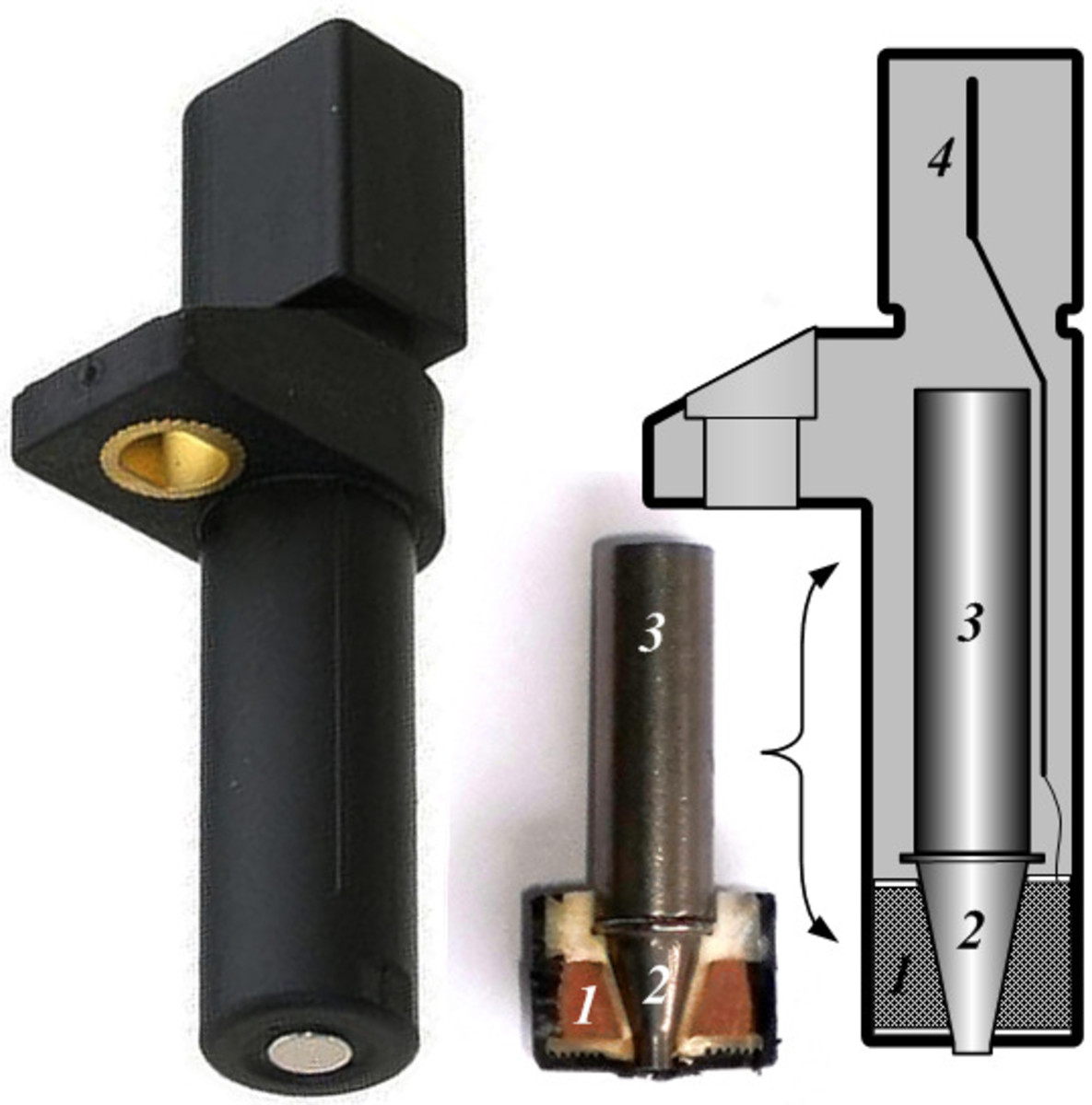
Forget that dc voltage on the purple wire. I’ve been researching what GM means by low reference and that seems to just be a ground provided through the pcm. That changes the way I have been thinking about this. It’s completely different from a typical 5v reference signal. I have been assuming that the test light should have lighting in step 6 of the diagnostic procedure. It should not have voltage unless the motor is turning to generate it. So either the voltage of 2.5 volts is just stray voltage and not a problem or there is a short to voltage that is a problem (possibly in the pcm itself). If you go back to the diagnostic procedure and use the test light as not coming on, you then go to step 11 which is checking pcm connection. Nothing found goes next to step 17 which is replace the pcm.

Of course this assumes that the fault is currently happening but you indicate that it happens after driving for a few minutes. I would still run new wire from the pcm to the sensor to eliminate the possibility of an intermittent wire problem. After that it’s probably a pcm replacement. If you have to go that route, someone with HPTUNER can read your current fIle and then change the calibration in the new pcm.
 
Last edited:
lksohm
I already have the new sensor installed. I banged up the original while removing it.

I am getting nearly identical readings from both yellow and purple wires.
Both are getting 2.5V DC and about 3VAC with ignition on, this goes to zero after about 30 seconds of the key off.

I started the engine and measured the frequency. I am getting about 1000 Hz at idle and it seems to follow the tach with some use of the gas pedal.
This is the same on both signal and low reference lines.

I'll see what I can do to get a shielded, twisted pair cable to run my own line.

I am really learing to love my new Fluke 87V BTW
 
G
I made major edits my previous post at the same time you were posting. It sounds like the 2.5vDC and 3vAC is stray current but I don't know if that is a problem or not. It sounds like the ckp is working. Are you getting the 1000 hz at the PCM?
 
Last edited:
lksohm
The 1000Hz was taken directly out of the PCM connector. It seems to change with engine rpm, exactly as I understand it should.
I will reach out to a cobalt DIY tuner a few hours from me to see if he can move my tune over to a new PCM.
At this point the $200 or so for the PCM is seeming insignificant.
 
Ross
If your PCM isn't password protected (some tuners lock the PCM) then anyone with HP Tuners can download your existing tune, and upload it to a new PCM. HP Tuners charges $100 to licence a new VIN, which is needed to upload to the new PCM.
 
Back
Top