
- G-Quest Member
Hello all, Ken here, #268 ext. city, 2006 SS/SC with several electrical questions. The donor was alive and well before disassembly – I put about 5,000 miles on it waiting for COVID pass us by.
After assembling the Goblin I plugged in the battery and found that I, at best, scored a C- in wiring.
Things that worked:
* Lights – High/Low beams, turn signals, running lights, dash lights
* Horn
* Intercooler fan
* Several dash indicator lights (MIL, security)
* Throttle body butterfly
* Starter (will spin the engine whether the clutch is in or out)
Things that didn’t work:
* No gage responses
* Wouldn’t start
* Couldn’t get the fuel pump to prime
Tried to throw my old HF code reader on the OBDII and it wouldn’t connect. So, what’s a guy to do – search the DF Forum, of course.
I, like several others, (I’ve since discovered) went a little overboard when following instructions on the wiring video to solder all of the dark green (GMLAN) wires together and ended up with continuity between pin 1 and 2 on the ODBII connector. Seeing that, I thought I should look more closely at all of the info networks to make sure there were no other goofs.
After pouring over the schematics on Alldatadiy (bless you @Ross) I’ve put together what I believe to be the connections for the 2006 SS/SC GMLANs. If anyone out there more skilled in the electrical arts could take a look and see if I’m on the right track I would appreciate it.
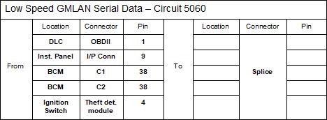
I found the wire for BCM / C2 / Pin 38 cut when looking around. I don’t have a digital radio and I’m not sure what a VCIM is or whether it still exists so I’m not sure if I need to reconnect the wire or not. Other data circuits:

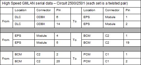
After verifying the above connectivity there were only a few changes in the win/loss categories - I did get the reader to throw a fuel system code. No gauges, no gas, no starting.
Now the questions:
* Does the above look correct? Any modifications, deletions, additions or suggestions (e.g. take up knitting instead of building a Goblin)?
I think I may have fried something in the fuse box when trying to jump the fuel pump the second time. I did verify +12v coming up to the relay connection and continuity between the fuel pump power supply wire (pin B) and the power feed wire in the fuse block (connector C2 pin D4) but no joy in getting voltage through the relay to the pump for the key-on prime.
* Can anyone share with me the steps to disassemble the fuse box and inspect/repair the little devil? At first glance it doesn’t look like it wants to come apart easily.
* Has anyone developed a “continuity checklist” similar to the above tables for the Goblin harness modifications? Looking back I would have gladly spent a couple of hours with the harness on the table checking my work vs. diagnosing issues in the car.
If there are no easy fixes I'll probably yank the harness back out and step-by-step verify continuity of all harness mods. Yikes – knitting isn’t sounding so bad…
After assembling the Goblin I plugged in the battery and found that I, at best, scored a C- in wiring.
Things that worked:
* Lights – High/Low beams, turn signals, running lights, dash lights
* Horn
* Intercooler fan
* Several dash indicator lights (MIL, security)
* Throttle body butterfly
* Starter (will spin the engine whether the clutch is in or out)
Things that didn’t work:
* No gage responses
* Wouldn’t start
* Couldn’t get the fuel pump to prime
Tried to throw my old HF code reader on the OBDII and it wouldn’t connect. So, what’s a guy to do – search the DF Forum, of course.
I, like several others, (I’ve since discovered) went a little overboard when following instructions on the wiring video to solder all of the dark green (GMLAN) wires together and ended up with continuity between pin 1 and 2 on the ODBII connector. Seeing that, I thought I should look more closely at all of the info networks to make sure there were no other goofs.
After pouring over the schematics on Alldatadiy (bless you @Ross) I’ve put together what I believe to be the connections for the 2006 SS/SC GMLANs. If anyone out there more skilled in the electrical arts could take a look and see if I’m on the right track I would appreciate it.
I found the wire for BCM / C2 / Pin 38 cut when looking around. I don’t have a digital radio and I’m not sure what a VCIM is or whether it still exists so I’m not sure if I need to reconnect the wire or not. Other data circuits:
After verifying the above connectivity there were only a few changes in the win/loss categories - I did get the reader to throw a fuel system code. No gauges, no gas, no starting.
Now the questions:
* Does the above look correct? Any modifications, deletions, additions or suggestions (e.g. take up knitting instead of building a Goblin)?
I think I may have fried something in the fuse box when trying to jump the fuel pump the second time. I did verify +12v coming up to the relay connection and continuity between the fuel pump power supply wire (pin B) and the power feed wire in the fuse block (connector C2 pin D4) but no joy in getting voltage through the relay to the pump for the key-on prime.
* Can anyone share with me the steps to disassemble the fuse box and inspect/repair the little devil? At first glance it doesn’t look like it wants to come apart easily.
* Has anyone developed a “continuity checklist” similar to the above tables for the Goblin harness modifications? Looking back I would have gladly spent a couple of hours with the harness on the table checking my work vs. diagnosing issues in the car.
If there are no easy fixes I'll probably yank the harness back out and step-by-step verify continuity of all harness mods. Yikes – knitting isn’t sounding so bad…


