duthehustle93
Well-Known Member
- duthehustle93 Well-Known Member
Hi All,
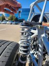
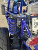
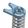
It seems that several people who are running coilovers have snapped the top of their damper off. A McPherson setup uses the damper as a suspension member, so this failure mode can be dangerous if it happens on track, or at a high speed. Since the lower control arm moves on an arc, the top of the damper should be free to pivot... OEM's solve this by isolating the top of the damper shaft from the body with a bushing, and performance aftermarket typically opts for a spherical mount/coaxial mount/pillowball mount. Cyclic bending loads, a large stress riser at either the thread root or damper shoulder, and a hardened and hollow damper shaft all contribute to this failure.
I have a plan to make a one-off on a bridgeport for me, but I was debating designing something nicer and having a large batch made. If there's enough interest (~10 sets would be the minimum to where it starts to get cheap enough to manufacture) I can start polishing off the design for manufacturing. This will be a bolt-in solution that replaces the black anodized aluminum plate shown in the picture.
This will only apply to people running coilovers, or sleeved dampers. Sorry, I don't think this issue happens as often (if ever?) to people with stock dampers, and the design I have mocked up works better with standard 2.5" coilover springs. Final design and prototypes will be posted up before asking for any money.
The primary benefit of this is not snapping damper shafts. The secondary benefit is a reduction in binding and friction induced within the damper. This will have some performance and longevity benefits to the damper, although it may not be significant enough to be noticeable.
Options:
____________________________________________________________________________________________________
Current status: I'm in process of setting up a second smaller batch. Group buy pricing is over, and I don't get the same bulk discounting for this batch, so pricing will be $295/kit shipped. If you are interested, please PM me. This will be the last batch of these made.
Design
Timeline
Install instructions
STL's/spare parts/documents
__________________________________________________________________________________________________
BC standard mount 0° offset:
This project has been more of a passion project than anything; after assembly time it’s basically break-even. A lot of care has gone into the design, including FEA and validation of the hardware, bearings, and fits with a target FOS > 3 under a 3G bump scenario.
That said, as with any performance-oriented suspension component, I want to be clear about intended use and responsibility:
It seems that several people who are running coilovers have snapped the top of their damper off. A McPherson setup uses the damper as a suspension member, so this failure mode can be dangerous if it happens on track, or at a high speed. Since the lower control arm moves on an arc, the top of the damper should be free to pivot... OEM's solve this by isolating the top of the damper shaft from the body with a bushing, and performance aftermarket typically opts for a spherical mount/coaxial mount/pillowball mount. Cyclic bending loads, a large stress riser at either the thread root or damper shoulder, and a hardened and hollow damper shaft all contribute to this failure.
I have a plan to make a one-off on a bridgeport for me, but I was debating designing something nicer and having a large batch made. If there's enough interest (~10 sets would be the minimum to where it starts to get cheap enough to manufacture) I can start polishing off the design for manufacturing. This will be a bolt-in solution that replaces the black anodized aluminum plate shown in the picture.
This will only apply to people running coilovers, or sleeved dampers. Sorry, I don't think this issue happens as often (if ever?) to people with stock dampers, and the design I have mocked up works better with standard 2.5" coilover springs. Final design and prototypes will be posted up before asking for any money.
The primary benefit of this is not snapping damper shafts. The secondary benefit is a reduction in binding and friction induced within the damper. This will have some performance and longevity benefits to the damper, although it may not be significant enough to be noticeable.
Options:
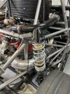
- Standard spherical mount: spherical mount for the damper w/ integrated spring perch. This will get rid of the parts hamburger that you stack for the spring perch, as the perch will be integrated into the plate. The new plate will have a pocket in the center of the spring that accepts a replaceable spherical bearing that the damper will bolt to.
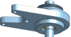
Initial group buy pricing is $250 per set shipped(includes 2x anodized plates, 2x spherical bearings, and any required additional hardware). coaxial mount. This will use the DF supplied strut spacer and spring perch. This mount will place both the spring and damper shaft on the spherical bearing, holding the spring and damper coaxial. The advantage of this is the spring won't banana at all, resulting in a slightly more linear spring rate. The downside is that the spherical bearing may wear out faster, and it's going to take me more time to develop this. If I'm honest, there is some performance gain with coaxial mounts, but it's marginal in my experience. ~$350 per set shipped (includes 2x anodized plates, 2x spherical bearings, and any required additional hardware).additional camber option: I'm assuming most of you are running crash bolts, eccentric bolts, or are slotted. I'm also assuming that most of you are near or at the top of your adjustment range, I certainly am. I am considering moving the mount point inboard to increase negative camber, if that's something that people need.
____________________________________________________________________________________________________
Current status: I'm in process of setting up a second smaller batch. Group buy pricing is over, and I don't get the same bulk discounting for this batch, so pricing will be $295/kit shipped. If you are interested, please PM me. This will be the last batch of these made.
Design
Timeline
Install instructions
STL's/spare parts/documents
__________________________________________________________________________________________________
BC standard mount 0° offset:
Gtstorey (paid)Comegetjoe (paid)Jaredthenav (paid)SmsDetroit (paid)Rttoys (paid)-Markm(paid)Indy Lonnie (paid)-OptimizePrime (paid)Sparvy(paid)WYGoblin (paid)ToxicBill (paid)KSLunsfo (paid)Meansol (paid)[me] *modified for 14mm shaft*95Blitz (paid)David (paid)Stretch2126 (paid)gofast (paid)GearHeadzGarage (paid)Owenmachine (paid)RobC76 (paid)Keckster (paid)Jason d (paid)
This project has been more of a passion project than anything; after assembly time it’s basically break-even. A lot of care has gone into the design, including FEA and validation of the hardware, bearings, and fits with a target FOS > 3 under a 3G bump scenario.
That said, as with any performance-oriented suspension component, I want to be clear about intended use and responsibility:
- These parts are intended for off-road, racing, or competition use only
- Installation and use inherently involve risk
- Proper installation (including correct torque and hardware) is critical
- The end user assumes responsibility for installation, use, and ongoing inspection
Attachments
-
 574609826_10163448520224190_5792163123176906125_n.jpg323.2 KB · Views: 236
 -
 575163748_10164119310152990_7494306366938101360_n.jpg342.3 KB · Views: 237
 -
 Screen Shot 2026-03-08 at 2.48.53 PM.png253.7 KB · Views: 118
 -
 IMG_1257.jpeg456 KB · Views: 110
 -
 Screenshot 2026-03-11 095543.png345.6 KB · Views: 112
 -
 bottom.png299.5 KB · Views: 77
 -
 CS.png440 KB · Views: 71
Last edited:
